Flow Calculation from Pressure Differential Devices
Symbols
Expansion Factor
Discharge Coefficient and Flow Coefficient
Flow Equation
When installation requirements and flow conditions from ISO 5167 are met, standardized flow devices can provide flow rate results with good accuracy.
The diameter ratio is defined
β = dD (1)
The Reynolds number, expressing the ratio between the inertia and viscous forces in the upstream pipe is
ReD = m0.25 π μ1 D (2)
Symbols
Expansion Factor
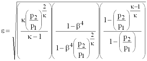
The expansion factor takes into account the compressibility of the fluid.
Orifice plates
 (9.3)
(9.3)
Nozzles, Venturi nozzles, Venturi tubes
 (9.4)
(9.4)
Discharge Coefficient and Flow Coefficient
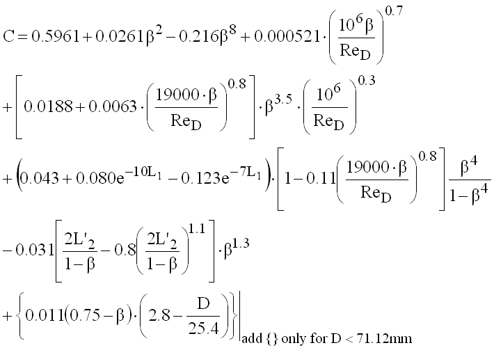
The discharge coefficient is defined for an incompressible fluid flow and relates actual vs. theoretical flowrate.
Orifice plates
 (9.5)
(9.5)
Corner tappings: L1 = L'2 = 0
Flange tappings: L1 = L'2 = 25.4/D with D [mm]
D and D/2 tappings: L1 = 1; L'2 = 0.47
ISA 1932 Nozzles
 (9.6)
(9.6)
Long radius nozzles
 (9.7)
(9.7)
Venturi nozzles
 (9.8)
(9.8)
Classical venturi tubes with an »as cast« convergent section
 (9.9)
(9.9)
Classical venturi tubes with a machined convergent section
 (9.10)
Classical venturi tubes with a rough-welded sheet-iron convergent section
 (9.11)
Discharge coefficient and flow coefficient are related
 (9.12)
Flow Equation
Where the discharge coefficient depends on the Reynolds number the mass flow can only be found by iteration.
 (9.13)
